|
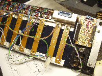
This is the back of the control panel. The biggest problem with sliders is dirt.
You can see here that I have glued a layer of blue felt behind the sliders, and
cut a line for each slider with a very sharp scalpel. This should keep most of
any dust or dirt, out. The horizontal blue IDC connects to the bargraph leds.
The small veroboard on the right carries six buttons for different light patterns.
|
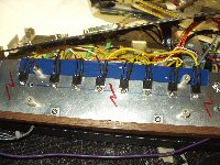
These are the Triacs that power the 240v lights. The aluminium that they
are mounted on is a thick old slab, around 4mm thick. I spent hours trying
to decide how to work this bit for safety (mine). In the end I went for this,
the Triacs are all commoned here to Mains LIVE, so the heatsink is also LIVE,
but contained inside the controller.
|
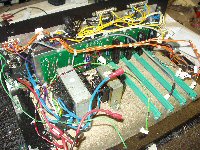
A general view of the innards. The backplane was recovered from something I
built years ago, and a few patches made for it to work in this project.
There is a 12v regulator on the backplane which powers all the boards except
the AGC board which has an on board 5v (for the PIC). As no other board needs
5v I decided this was the best way. The smaller transformer is all that is needed
to run the controller. The larger one is a 12v supply for my secondary Triacs.
|
|
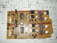
There are two trigger boards. Each board controls four channels.
Four Triacs are mounted on ther board, intended for low power/low voltage
testing. Four more Triacs are mounted on the big heatsink at the back.
You can see the three windings on the pulse transformers - they are not
difficult to wind.
|
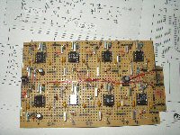
A bank of simple 2 pole active filters, each spaced an octave apart.
The compressed audio is the input and a rectified output controls a trigger.
|
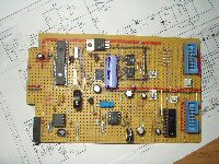
This is the AGC and PIC board. Bottom right is the bargrahp driver, and the opto
next to the big cap in the middle is part of my zero crossing signal. PIC top left
which generates a number of chase patterns. Down the bottom is the AGC circuit which
ensures a steady amplitude signal to the active filters.
|
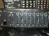
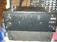 Every Disco in the 70s had to have a light show and usually this meant
a Projector or two, and a Sound-To-Light system. There were a number of
popular Eelctronics magazines back then and they all ran regular features
about building these things. I built two before I finally built what was
something of a standard in its day : The Practical Electronics 'Aurora'.
